Project TELEGRAPH (Part 2): Escaping the Cables with a Custom ESP32 Wireless Flasher
Overview
1. The Reality of Reverse Engineering
Let’s be honest: the reality of hardware reverse engineering usually involves sitting hunched over a cluttered desk, tethered to your target device by a short USB cable, constantly manually resetting the board. I don't have much space on my desk, and I absolutely despise cable clutter.
If we are going to treat this cheap clock as a node in the MekOps ecosystem, we need to treat it like remote infrastructure. No physical interaction, no power cycling by hand.
Fortunately, the clock's STM32 microcontroller has a built-in savior: a ROM-based bootloader that supports the
AN3155 USART protocol. I quickly verified this by hooking up a USB-UART adapter and using
stm32flash to successfully dump the original firmware. It worked,
but it still required wires.
It was time to build a wireless bridge.
2. The Hardware: Waveshare ESP32 One
To add wireless connectivity to the clock, I dug into my parts bin and pulled out a Waveshare ESP32 One.
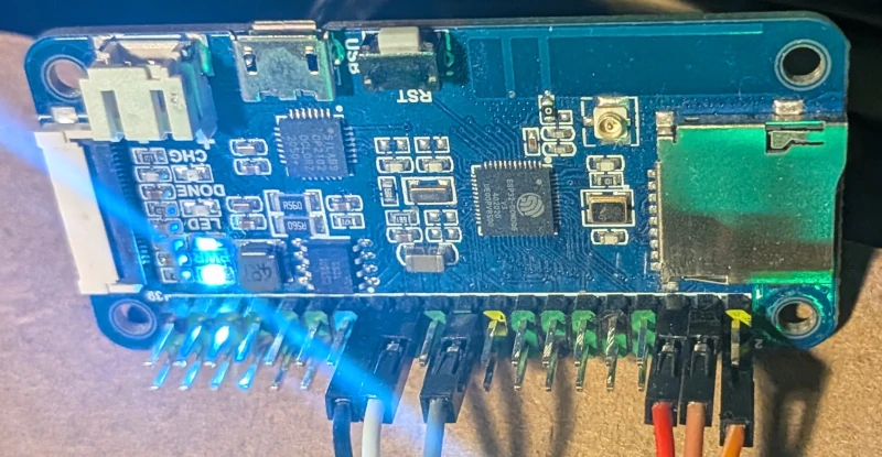
I chose this specific board for a few reasons: it was leftover from a previous experiment, it has a Raspberry Pi-compatible GPIO header (which makes connecting things quite easy), and it packs plenty of PSRAM. I have some further plans for this device in the future, so the extra memory will come in handy.
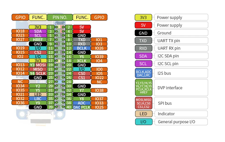
The Critical Connections
To achieve true "zero-touch" flashing, you can't just connect TX and RX. You need hardware lifecycle control. I wired the ESP32 to the STM32 as follows:
| One pin | STM32 pin | Note |
|---|---|---|
| IO 13 (RX) | UART TX | ESP32 sends to STM32 |
| IO 14 (TX) | UART RX | ESP32 receives from STM32 |
| IO 23 | BOOT0 | Bootloader Control: pulls the STM32 into bootloader mode during the reset sequence |
| IO 18 | NRST | Reset Control of the STM32 |
3. The Failed Attempt: Socat and serial to tcp bridge
My first instinct was to avoid reinventing the wheel. The plan was to flash the ESP32 with Tasmota, configure its
ser2net-like feature (Serial-to-TCP bridge), and pipe it into my
local Linux machine using socat to create a virtual COM port.
I spun up the link:
1socat -d -d pty,link=/tmp/vcom0,raw,echo=0 tcp:192.168.1.XX:8888
And then fired the flasher at the virtual port:
1stm32flash -b 0 /tmp/vcom0
It failed spectacularly. The issue lies in how stm32flash interacts with the operating system. It tries to initialize
the port by setting baud rates and traditional serial ioctls. Because /tmp/vcom0 is a pseudo-terminal (pty) and not a
real hardware UART, the initialization fails.
I spent an hour or so, fiddling with stm32flash flags—using -b 0 to bypass baud rate settings, or -c to disable the
initial INIT sequence. socat's debug output showed the ESP32 was responding, but stm32flash would just hang,
waiting for an expected hardware state or STM32's response that a TCP bridge simply couldn't provide. I didn't want
to fight with this, since my plans for this were different.
I decided to stop. Time for Plan B.
4. Plan B: Building the Custom Flasher
If the host tools won't cooperate with a dumb TCP bridge, the intelligence needs to move to the edge. I decided to write a custom ESP32 firmware that natively understands the ST AN3155 bootloader protocol.
  graph LR
    A[Laptop] -- Firmware upload (HTTP) --> B[ESP32 Flasher]
    B -- AN3155 Protocol (UART) --> C[STM32 Target]
You can find the source code for this flasher in my repository here.
The Dual-Mode Server
The ESP32 firmware is designed to do two jobs simultaneously:
- Web Console (Port 80): Handles the OTA payload ingestion and orchestrates the
BOOT0/NRSTpin toggling.- It has additional feature to perform stm32 identify to check whether we have good connection and identify target.
- Raw TCP Bridge (Port 8888): Once the STM32 is booted into user code, this port acts as a transparent serial monitor
over the LAN (
ser2net-like).
This makes PlatformIO integration incredibly clean. You just add this to your platformio.ini to get live serial logs
over WiFi:
1monitor_port = socket://192.168.x.x:8888
5. The Deployment Pipeline
The final piece of the puzzle was automating the upload. I wrote a zero-dependency, pure-Python OTA upload script
(upload_script.py) that POSTs the compiled .bin file
directly to the ESP32's web server.
To tie it all together, I wired it into PlatformIO as a custom upload protocol. My experimental firmware repository uses this exact setup.
1; platformio.ini
2upload_protocol = custom
3extra_scripts = upload_script.py
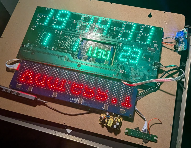
The Climax
With the script in place, I hit "Upload" in VS Code.
The Python script grabbed the binary, shot it over WiFi to the ESP32. The ESP32 pulled BOOT0 high, yanked NRST low, and
streamed the payload directly into the STM32's flash memory using the AN3155 protocol. A few seconds later, BOOT0
dropped, the board reset, and my test code was running.
No cables. No manual resets. Just a rock-solid, wireless deployment pipeline.
Now that we have full remote control over the silicon, the real hacking begins. In the next part, we will start writing the actual firmware snippets to map out the matrix and bring this display back to life.
Posts in this series
- Project TELEGRAPH (Part 1): Rescuing a $15 LED Matrix from Software Purgatory
- Project TELEGRAPH (Part 2): Escaping the Cables with a Custom ESP32 Wireless Flasher
- Project TELEGRAPH (Part 3): Bare Metal, Bit-Banging, and the 4MB Heist